Hallo Tobi,
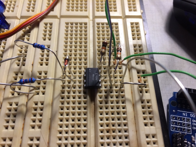
man kann es auf dem Bild nicht 100%ig erkennen, aber mir scheint, dass die Schutzdiode am Eingang des Optokopplers falsch herum eingesteckt ist. Dann wird die Led im Optokoppler nicht leuchten und - noch schlimmer - kann sie sogar kaputtgehen, da sie jetzt nicht mehr vor der hohen Sperrspannung geschützt wird (wozu die Diode ja dient). Ob sie das überlebt hat ist Glücksache.
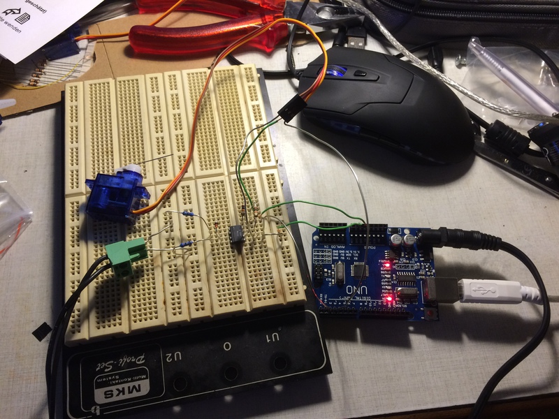
Ausserdem sieht es so aus, als wenn Du die gesamte Schaltung - einschließlich des Servos - aus dem USB-Anschluß versorgst. Da könnte das Servo mit dem Anlaufstrom den USB-Anschluß evtl. überfordern.
RE: z21, Arduino Uno3, Weichensteuerung, Adafruit, Servo, gelöst!!!!!
viele Grüße
Franz-Peter
Ein 'elektromechanisches' Stellwerk
Der (ehemalige) 'Eisberg'
- MicroBahner
- Metropolitan (MET)
-
Beiträge: 2.833 Registriert am: 28.11.2012 Ort: Mittelfranken Gleise Tillig Elite Steuerung Eigenbau Stromart Analog

RE: z21, Arduino Uno3, Weichensteuerung, Adafruit, Servo, gelöst!!!!!
Lebe im Moment, freue dich auf die Zukunft
- tobi_bahner
- InterRegioExpress (IRE)
-
Beiträge: 259 Registriert am: 01.05.2016 Spurweite N Stromart DC, Digital

RE: z21, Arduino Uno3, Weichensteuerung, Adafruit, Servo, gelöst!!!!!
Hmm.. nun wird's mit der Ferndiagnose langsam etwas schwierig  . Welche Möglichkeiten etwas zu messen hast Du denn? Hast Du ein Multimeter?
Wenn ja, dann geh mal mit der Zentrale auf STOP und miss die Spannung an Pin2 des UNO. Da sollten dann etwa 5V anliegen. Nun schalte die Gleisspannung wieder ein. Dann muss die gemessene Spannung deutlich kleiner werden - so ca. die Hälfte. Wenn nicht, funktioniert deine DCC Eingangsschaltung noch nicht.
viele Grüße
Franz-Peter
Ein 'elektromechanisches' Stellwerk
Der (ehemalige) 'Eisberg'
- MicroBahner
- Metropolitan (MET)
-
Beiträge: 2.833 Registriert am: 28.11.2012 Ort: Mittelfranken Gleise Tillig Elite Steuerung Eigenbau Stromart Analog

RE: z21, Arduino Uno3, Weichensteuerung, Adafruit, Servo, gelöst!!!!!
eben haben 2 Ingenieure auf die Schaltung geschaut und festgestellt, dass keine 510 ohm Widerstände verbaut waren, sondern 500k. 

 Jetzt funktioiniert der Servo!!
morgen probiere ich die anderen Sketche aus!!
Lebe im Moment, freue dich auf die Zukunft
- tobi_bahner
- InterRegioExpress (IRE)
-
Beiträge: 259 Registriert am: 01.05.2016 Spurweite N Stromart DC, Digital

RE: z21, Arduino Uno3, Weichensteuerung, Adafruit, Servo, gelöst!!!!!
es funktioniert nun so wie es soll!!
außer auf Steckplatz 1 für den Servo. Meine Adressierung fängt erst ab Steckplatz 2 an.
Nichts desto trotz lässt sich einfach jedes Servo programmieren und ansteuern!
Vielen herzlichen Dank an alle die mitgeholfen haben!
der Aufbau ist der, der hier im Thread beschrieben wird.
der passende Sketch für 15 Servos ist dieser:
2
3
4
5
6
7
8
9
10
11
12
13
14
15
16
17
18
19
20
21
22
23
24
25
26
27
28
29
30
31
32
33
34
35
36
37
38
39
40
41
42
43
44
45
46
47
48
49
50
51
52
53
54
55
56
57
58
59
60
61
62
63
64
65
66
67
68
69
70
71
72
73
74
75
76
77
78
79
80
81
82
83
84
85
86
87
88
89
90
91
92
93
94
95
96
97
98
99
100
101
102
103
104
105
106
107
108
109
110
111
112
113
114
115
116
117
118
119
120
121
122
123
124
125
126
127
128
129
130
131
132
133
134
135
136
137
138
139
140
141
142
143
144
145
146
147
148
149
150
151
152
153
154
155
156
157
158
159
160
161
162
163
164
165
166
167
168
169
170
171
172
173
174
175
176
177
178
179
180
181
182
183
184
185
186
187
188
189
190
191
192
193
194
195
196
197
198
199
200
201
202
203
204
205
206
207
208
209
210
211
212
213
214
215
216
217
218
219
220
221
222
223
224
225
226
227
228
229
230
231
232
233
234
235
236
237
238
239
240
241
242
243
244
245
246
247
248
249
250
251
252
253
254
255
256
257
258
259
260
261
262
263
264
265
266
267
268
269
270
271
272
273
274
275
276
277
278
279
280
281
282
283
284
285
286
287
288
289
290
291
292
293
294
295
296
297
298
299
300
301
302
303
304
305
306
307
308
309
310
311
312
313
314
315
316
317
318
319
320
321
322
323
324
325
326
327
328
329
330
331
332
333
334
335
336
337
//////////////////////////////////////////////////////////////////////////////////////////////////////////////////////
// Arduino DCC Servo and Function Decoder.
// Author: Author: Ruud Boer - January 2015
// This sketch turns an Arduino into a DCC decoder with max 12 servo motor outputs combined with function outputs.
// The DCC signal is optically separated and fed to pin 2 (=Interrupt 0). Schematics: www.mynabay.com
// Many thanks to www.mynabay.com for publishing their DCC monitor and -decoder code, which is used in this sketch.
//
// Important Change:
// This sketch from Ruud Boer was changed by lordbrummi in April 2016
// Now you can connect a PWM Arduino Servo Shield with 16 possible servos and adress them with DCC adresses
//////////////////////////////////////////////////////////////////////////////////////////////////////////////////////


//////////////////////////////////////////////////////////////////////////////////////////////////////////////////////
// IMPORTANT: GOTO lines 22, 49, 72 to configure some data!
//////////////////////////////////////////////////////////////////////////////////////////////////////////////////////

#include <Wire.h>
#include <Adafruit_PWMServoDriver.h>

Adafruit_PWMServoDriver pwm = Adafruit_PWMServoDriver();

#include <DCC_Decoder.h>
#include <Servo.h>
#define kDCC_INTERRUPT 0

//////////////////////////////////////////////////////////////////////////////////////////////////////////////////////
// Fill in these 1 value ...
//////////////////////////////////////////////////////////////////////////////////////////////////////////////////////
const byte maxservos = 16; //The number of servos you have connected to this Arduino                    IMPORTANT!!!!!
//////////////////////////////////////////////////////////////////////////////////////////////////////////////////////
const byte servotimer = 40;

//////////////////////////////////////////////////////////////////////////////////////////////////////////////////////
// Set the Servomin and the Servomax of your servo between the gear range possibility                  IMPORTANT!!!!!
const int SERVOMIN = 150; // this is the 'minimum' pulse length count (out of 4096)
const int SERVOMAX = 600; // this is the 'maximum' pulse length count (out of 4096)
//////////////////////////////////////////////////////////////////////////////////////////////////////////////////////

unsigned long timetoupdatesetpoint = millis() + servotimer;


struct DCCAccessoryAddress {
  int address; // DCC address to respond to
  byte output; // State of accessory: 1=on, 0=off (for internal use only)
  int outputPin; // Arduino output pin
};
DCCAccessoryAddress accessory[maxservos];

struct servoItem {
  int angle;
  int setpoint;
  int offangle;
  int onangle;
  byte inverted;
  int servo;
  byte functionnumber;
};
servoItem servos[maxservos];

////////////////////////////////////////////////////////////////////////////////////////////////////////////////////////////////////////////////////
// Fill in the address and pin for every accessory / function. Servos are 'coupled' to accessory[n] in line 72 and further.           IMPORTANT!!!!!
// COPY - PASTE as many times as you have functions. The amount must be same as in line 22 above!
////////////////////////////////////////////////////////////////////////////////////////////////////////////////////////////////////////////////////
void ConfigureDecoderFunctions()
{
  accessory[0].address = 0;     // DCC address for this accessory
  accessory[0].outputPin = 13;  // Arduino pin where accessoryis connected to

  accessory[1].address = 1;     // DCC address for this accessory
  accessory[1].outputPin = 13;  // Arduino pin where accessory is connected to

  accessory[2].address = 2;     // DCC address for this accessory
  accessory[2].outputPin = 13;  // Arduino pin where accessory is connected to

  accessory[3].address = 3;     // DCC address for this accessory
  accessory[3].outputPin = 13;  // Arduino pin where accessory is connected to

  accessory[4].address = 4;     // DCC address for this accessory
  accessory[4].outputPin = 13;  // Arduino pin where accessory is connected to

  accessory[5].address = 5;     // DCC address for this accessory
  accessory[5].outputPin = 13;  // Arduino pin where accessory is connected to

  accessory[6].address = 6;     // DCC address for this accessory
  accessory[6].outputPin = 13;  // Arduino pin where accessory is connected to

  accessory[7].address = 7;     // DCC address for this accessory
  accessory[7].outputPin = 13;  // Arduino pin where accessory is connected to

  accessory[8].address = 8;     // DCC address for this accessory
  accessory[8].outputPin = 13;  // Arduino pin where accessory is connected to

  accessory[9].address = 9;     // DCC address for this accessory
  accessory[9].outputPin = 13;  // Arduino pin where accessory is connected to

  accessory[10].address = 10;     // DCC address for this accessory
  accessory[10].outputPin = 13;  // Arduino pin where accessory is connected to

  accessory[11].address = 11;     // DCC address for this accessory
  accessory[11].outputPin = 13;  // Arduino pin where accessory is connected to

  accessory[12].address = 12;     // DCC address for this accessory
  accessory[12].outputPin = 13;  // Arduino pin where accessory is connected to

  accessory[13].address = 13;     // DCC address for this accessory
  accessory[13].outputPin = 13;  // Arduino pin where accessory is connected to

  accessory[14].address = 14;     // DCC address for this accessory
  accessory[14].outputPin = 13;  // Arduino pin where accessory is connected to

  accessory[15].address = 15;     // DCC address for this accessory
  accessory[15].outputPin = 13;  // Arduino pin where accessory is connected to


  // Setup output pins for accessories
  for (int i = 0; i < maxservos; i++)
  {
    if ( accessory[i].outputPin )
    {
      pinMode (accessory[i].outputPin, OUTPUT );
      digitalWrite (accessory[i].outputPin, LOW);
    }
  }
} // END ConfigureDecoderFunctions


//////////////////////////////////////////////////////////////////////////////////////////////////////////////////////
// Fill in the attributes for every servo
// COPY - PASTE as many times as you have servo's. The amount must be same as maxservos in line 22 above!
//////////////////////////////////////////////////////////////////////////////////////////////////////////////////////
void ConfigureDecoderServos()
{
  servos[0].angle = 90;        //initial angle of servo. Make this the same as offangle to avoid startup jitter.
  servos[0].offangle = 90;     //minimum angle. Do not use value too close to 0, servo may stutter at the extremes.
  servos[0].onangle = 90;      //maximum angle. Do not use value too close to 180, servo may stutter at the extremes.
  servos[0].servo = 0;         //Arduino pin number where servo is connected to
  servos[0].functionnumber = 0; // CONNECTION BETWEEN FUNCTION AND SERVO ()accessory[functionnumber] - see above)

  servos[1].angle = 90;
  servos[1].offangle = 80;
  servos[1].onangle = 100;
  servos[1].servo = 1;
  servos[1].functionnumber = 1;

  servos[2].angle = 90;
  servos[2].offangle = 90;
  servos[2].onangle = 110;
  servos[2].servo = 2;
  servos[2].functionnumber = 2;

  servos[3].angle = 130;
  servos[3].offangle = 120;
  servos[3].onangle = 160;
  servos[3].servo = 3;
  servos[3].functionnumber = 3;

  servos[4].angle = 90;
  servos[4].offangle = 110;
  servos[4].onangle = 138;
  servos[4].servo = 4;
  servos[4].functionnumber = 4;

  servos[5].angle = 90;
  servos[5].offangle = 120;
  servos[5].onangle = 160;
  servos[5].servo = 5;
  servos[5].functionnumber = 5;

  servos[6].angle = 90;
  servos[6].offangle = 120;
  servos[6].onangle = 160;
  servos[6].servo = 6;
  servos[6].functionnumber = 6;

  servos[7].angle = 90;
  servos[7].offangle = 120;
  servos[7].onangle = 160;
  servos[7].servo = 7;
  servos[7].functionnumber = 7;

  servos[8].angle = 90;
  servos[8].offangle = 120;
  servos[8].onangle = 160;
  servos[8].servo = 8;
  servos[8].functionnumber = 8;

  servos[9].angle = 90;
  servos[9].offangle = 120;
  servos[9].onangle = 160;
  servos[9].servo = 9;
  servos[9].functionnumber = 9;

  servos[10].angle = 90;
  servos[10].offangle = 120;
  servos[10].onangle = 160;
  servos[10].servo = 10;
  servos[10].functionnumber = 10;

  servos[11].angle = 90;
  servos[11].offangle = 120;
  servos[11].onangle = 160;
  servos[11].servo = 11;
  servos[11].functionnumber = 11;

  servos[12].angle = 90;
  servos[12].offangle = 120;
  servos[12].onangle = 160;
  servos[12].servo = 12;
  servos[12].functionnumber = 12;

  servos[13].angle = 90;
  servos[13].offangle = 120;
  servos[13].onangle = 160;
  servos[13].servo = 13;
  servos[13].functionnumber = 13;

  servos[14].angle = 90;
  servos[14].offangle = 120;
  servos[14].onangle = 160;
  servos[14].servo = 14;
  servos[14].functionnumber = 14;

  servos[15].angle = 90;
  servos[15].offangle = 120;
  servos[15].onangle = 160;
  servos[15].servo = 15;
  servos[15].functionnumber = 15;


  // A servo is coupled to an accessory[n]. It rotates based on accessory[n].output = 1 or 0
  // If you have multiple servos you need to couple them to different accessories. However ...
  // accessories may switch the same output pin (e.g. pin 13, which has the on board led attached)

} // END ConfigureDecoderServos

//////////////////////////////////////////////////////////////////////////////////////////////////////////////////////
// DCC packet handler
//////////////////////////////////////////////////////////////////////////////////////////////////////////////////////
void BasicAccDecoderPacket_Handler(int address, boolean activate, byte data)
{
  // Convert NMRA packet address format to human address
  address -= 1;
  address *= 4;
  address += 1;
  address += (data & 0x06) >> 1;

  boolean enable = (data & 0x01) ? 1 : 0;

  for (int i = 0; i < maxservos; i++)
  {
    if (address == accessory[i].address)
    {
      if (enable) accessory[i].output = 1;
      else accessory[i].output = 0;

    }
  }
}

//////////////////////////////////////////////////////////////////////////////////////////////////////////////////////
// Setup (run once)
//////////////////////////////////////////////////////////////////////////////////////////////////////////////////////
void setup()
{
  DCC.SetBasicAccessoryDecoderPacketHandler(BasicAccDecoderPacket_Handler, true);
  ConfigureDecoderFunctions();
  ConfigureDecoderServos();
  DCC.SetupDecoder( 0x00, 0x00, kDCC_INTERRUPT );
  pinMode(2, INPUT_PULLUP); //Interrupt 0 with internal pull up resistor (can get rid of external 10k)
  //pinMode(A5,INPUT_PULLUP); //If made LOW, all servos go to their min angle, to avoid jitter at starup.      - Not to use with PWM Servoshield because it uses already pinMode A5
  pinMode(13, OUTPUT);
  digitalWrite(13, LOW); //switch off Arduino led at startup

  for (int n = 0; n < maxservos; n++)
  {
    pinMode(accessory[n].outputPin, OUTPUT); //Set accessory pins to OUTPUT mode
    servos[n].onangle = map(servos[n].onangle, 0, 180, SERVOMIN, SERVOMAX);   // Adjust the angles to the range given by Servomin and Servomax
    servos[n].offangle = map(servos[n].offangle, 0, 180, SERVOMIN, SERVOMAX);
    servos[n].angle = map(servos[n].angle, 0, 180, SERVOMIN, SERVOMAX);
  }

  Serial.begin(9600);
  Serial.println("Los gehts");

  pwm.begin();

  pwm.setPWMFreq(60);  // Analog servos run at ~60 Hz updates

  yield();
}

//////////////////////////////////////////////////////////////////////////////////////////////////////////////////////
// Main loop (run continuous)
//////////////////////////////////////////////////////////////////////////////////////////////////////////////////////
void loop()
{
  static int addr = 0;


  DCC.loop(); // DCC library

  if ( ++addr >= maxservos ) addr = 0; // Next address to test

  // Set accessory output pin
  if (accessory[addr].output) digitalWrite(accessory[addr].outputPin, HIGH);
  else digitalWrite(accessory[addr].outputPin, LOW);

  // Every 'servotimer' ms, modify setpoints and move servos 1 step (if needed)
  if (millis() > timetoupdatesetpoint)
  {
    timetoupdatesetpoint = millis() + servotimer;
    for (int n = 0; n < maxservos; n++)
    {
      if (accessory[servos[n].functionnumber].output) servos[n].setpoint = servos[n].onangle;
      else servos[n].setpoint = servos[n].offangle;
      pwm.setPWM(servos[n].servo, 0, servos[n].setpoint);
    }
  }

  //////////////////////////////////////////////////////////////////////////////////////////////////////////////////
  // Move all servos to min position and set all function outputs to 0, to eliminate startup servo jerk current draw
  //////////////////////////////////////////////////////////////////////////////////////////////////////////////////

  //if (digitalRead(A5)==LOW) {for (int n=0; n<maxservos; n++) accessory[n].output = 0;}               - Not to use with PWM Servoshield because it uses already pinMode A5

} //END MAIN LOOP
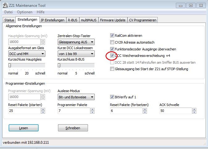
wichtig ist, dass bei der z21 dieses Häkchen hier gesetzt ist. 
Lebe im Moment, freue dich auf die Zukunft
- tobi_bahner
- InterRegioExpress (IRE)
-
Beiträge: 259 Registriert am: 01.05.2016 Spurweite N Stromart DC, Digital

RE: z21, Arduino Uno3, Weichensteuerung, Adafruit, Servo, gelöst!!!!!
Hallo Tobi,
Dein Eintrag im Stummiforum betrefend die Ansteuerung von Servos ist zwar schon vier Jahre alt, vielleicht kannst Du mir ja doch helfen.
Ich bin auf dem gleichen Weg, habe bereits den einfachen Accesory-Decoder am Laufen, nun kommen die Servos dran. Im Moment benutze ich einen einfachen Sketch zum Testen, mit welchem ich die Servos auf eine von der Konsole eingegebene Position stellen kann https://minhaskamal.github.io/DownGit/#/...ields%2FPCA9685.
Dabei sind mir zwei merkwürdige Dinge aufgefallen:
1. Nach einem Reset des Arduino (oder einer gleichwertigen Aktion) "zucken" die Servos kurz. Jedoch nur, wenn sie nicht auf Position "0" stehen.
2. Der Servo, welcher am Ausgang 0 des PCA 9685 angeschlossen ist, geht bei dieser Aktion in eine andere Stellung, und nur dieser.
Hast Du das auch beobachtet oder wird das von der Software von Boer/lordbrummi abgefangen?
Freundlich grüsst
Struwelpeter
- Struwelpeter52
-
Beiträge: 1 Registriert am: 09.03.2021


 ) verbaut.

